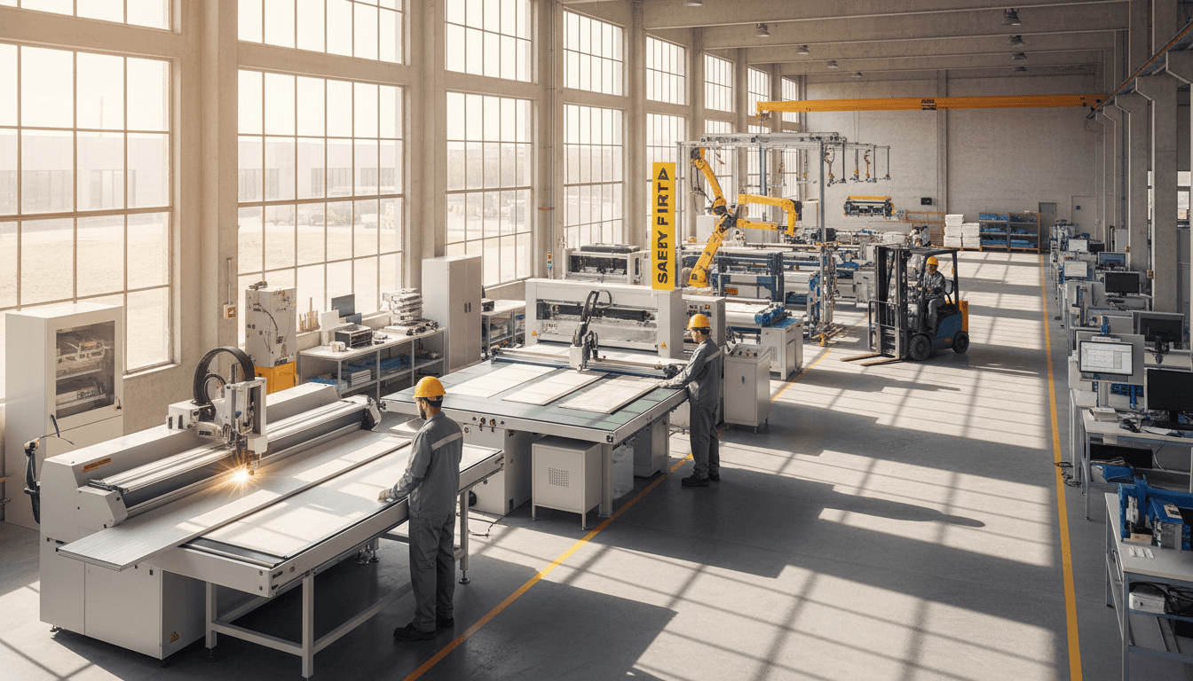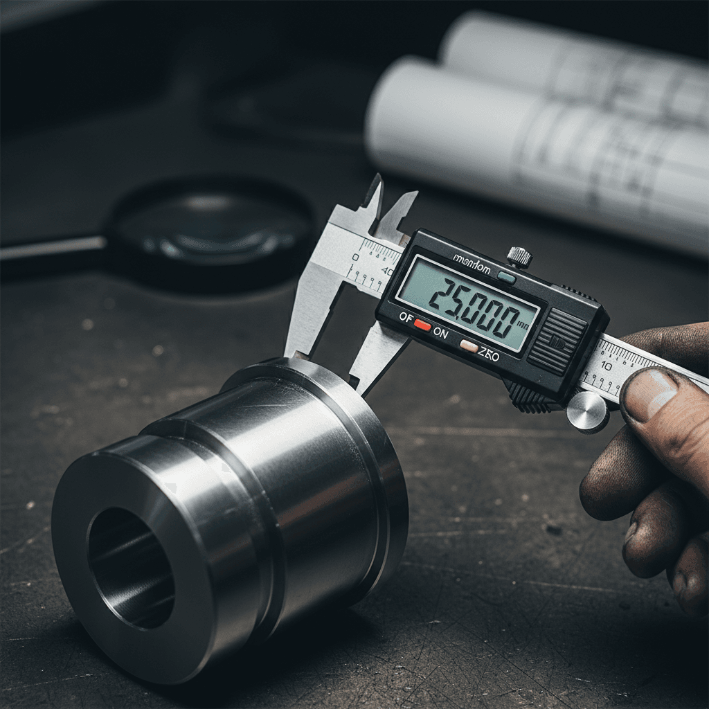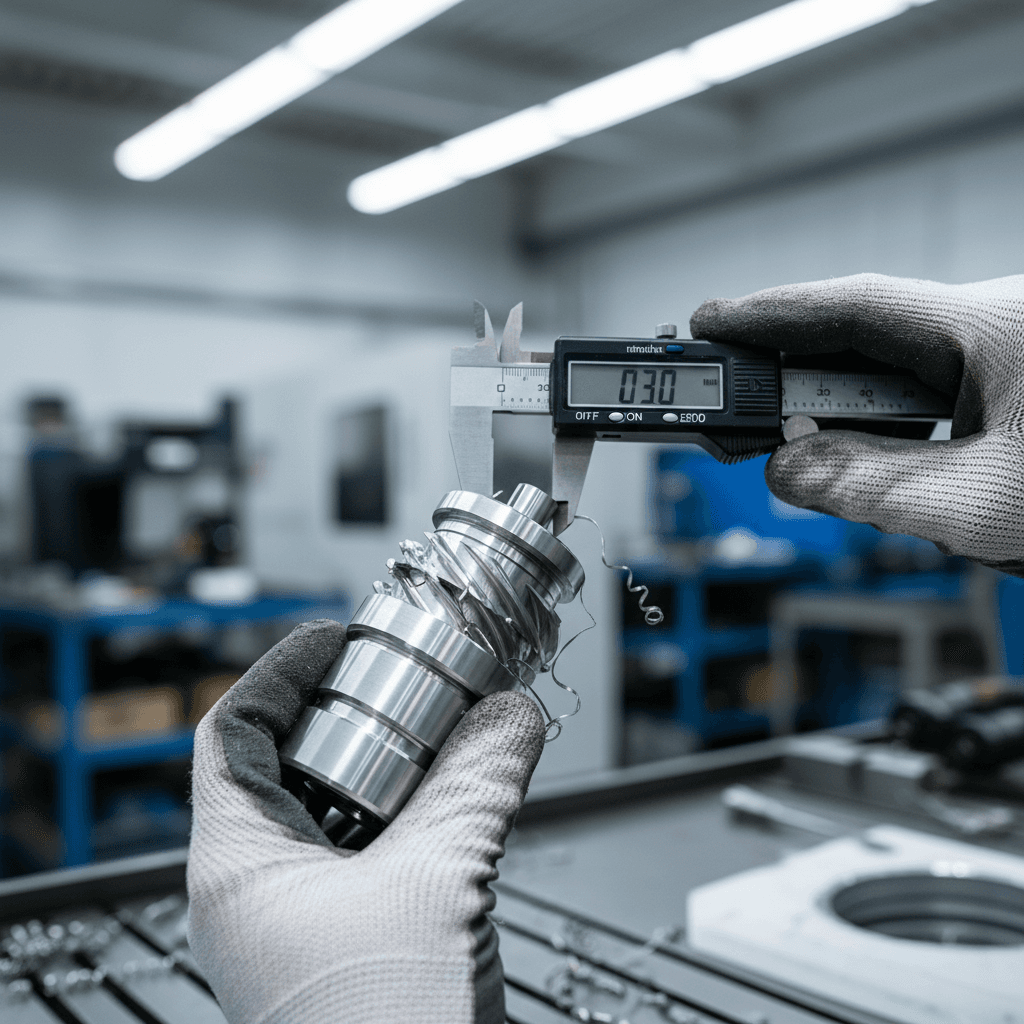
Design for manufacturability reduces production costs and lead times by optimizing part geometry and material selection for maximum fabrication efficiency. This practice minimizes material waste and eliminates unnecessary manufacturing steps; it ensures parts are produced consistently while avoiding expensive rework. By prioritizing ease of assembly during the engineering phase, companies can significantly accelerate their time to market.
Nothing erodes a project budget faster than a design that looks flawless on a screen but proves difficult or impossible to execute on the shop floor. For many engineers and procurement teams, the transition from CAD model to physical component is often fraught with unexpected revisions, production delays, and ballooning costs. This friction usually indicates a disconnect between initial design intent and the practical realities of modern metal fabrication. By integrating Design for Manufacturability principles early in the development process, you can eliminate these bottlenecks before they ever reach the machine. This article examines the core principles of DFM, offering practical guidelines for optimizing sheet metal and CNC machining projects to ensure maximum efficiency. We will also explore how collaborative design reviews with your fabrication partner can drastically shrink lead times and improve your bottom line.
What is Design for Manufacturability and Why Does It Matter?

Design for manufacturability is the practice of refining a product’s design to simplify production and ensure repeatable quality. While generic design focuses primarily on a part’s form and function, DFM accounts for the physical realities of the shop floor. It bridges the gap between a clean digital model and the actual fabrication process; it ensures that a part is not only functional but also economical to produce. By prioritizing DFM, we look for ways to eliminate unnecessary complexity that adds time and expense without improving the final product’s performance.
Understanding the impact of design requires looking at the three primary manufacturing costs:
Material Costs: This includes the raw stock used and the waste, or scrap, generated during processes like laser cutting or machining.
Labor Costs: These encompass the time spent by technicians on machine setup, operation, manual finishing, and skilled fabrication and assembly.
Overhead and Tooling Costs: These involve specialized equipment, custom dies, or unique fixtures required to handle complex geometries.
Industry data indicates that up to 70 percent of a product’s final manufacturing cost is determined during the design phase. Once a drawing is finalized, the majority of the production budget is already committed. By focusing on dependable manufacturing and production solutions early in the process, engineers can identify cost drivers before the first piece of metal is cut. Optimizing for the specific constraints of CNC machines and press brakes allows for higher material yields and faster throughput, turning the design stage into the most critical leverage point for profitability and long term performance.
Core Principles of DFM for Metal Fabrication
Transitioning from theoretical cost savings to shop floor execution requires adherence to foundational principles that bridge the gap between engineering and fabrication. Effective design for manufacturability starts with component standardization. By utilizing off-the-shelf fasteners and standard hardware rather than custom-machined pins or proprietary fittings, engineers eliminate the need for specialized tooling and reduce lead times. Standardizing these elements ensures that skilled fabrication and assembly remain streamlined, as technicians can work with familiar components that are readily available in inventory.
Material yield optimization is another critical lever for controlling costs. In both CNC machining and sheet metal work, how a part is oriented within the raw stock determines the amount of waste generated. Advanced nesting software allows us to pack parts tightly on a single sheet of steel or aluminum, but the design itself must support this. For example, parts designed with interlocking shapes or straight edges that allow for shared cuts can significantly reduce scrap, directly lowering the material cost per unit.
One of the most impactful principles is the Rule of Ten regarding tolerances. There is an exponential relationship between precision and price; typically, each significant tightening of a tolerance can increase production costs by a factor of ten. If a design specifies a tolerance of +/- .001 inches where +/- .005 would suffice, it necessitates slower feed rates, more frequent tool offsets, and specialized metrology equipment. Over-specifying tolerances adds machine time and inspection labor without improving the real-world performance of the component.
Finally, a successful design must move beyond a visually clean CAD model to become a production-ready file. A generic model often treats corners as perfect 90-degree angles and ignores the physical displacement of metal during forming. Production-ready files incorporate specific bend allowances and k-factors that account for the material thickness and the specific radius of the press brake tooling. By acknowledging these physical constraints during the design phase, engineers ensure that the final product matches the digital intent without requiring multiple prototypes or manual adjustments on the shop floor.
Sheet Metal Design Guidelines for Cost Reduction
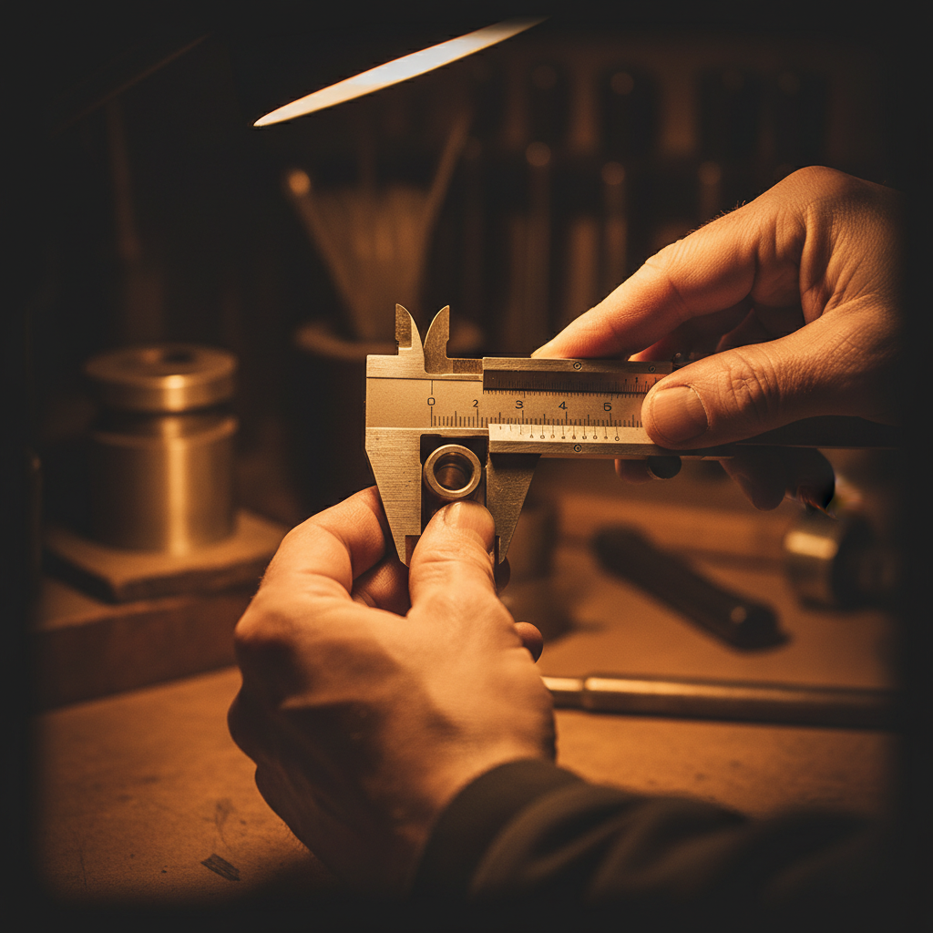
Applying these core principles specifically to sheet metal requires a granular look at how material behaves under a press brake. While modern equipment is versatile, the most efficient designs respect the physical limits of the forming process. A primary consideration is the inside bend radius. As a standard rule, the inside radius should at least equal the material thickness. Attempting to force a tighter radius requires specialized sharp tooling that can lead to material cracking or excessive stress; conversely, oversized radii often require custom setups that increase the cost per part.
Engineers should also evaluate feature placement relative to those bends. Holes and slots placed too close to a bend line will inevitably distort as the metal stretches. To maintain structural integrity and visual quality, keep all holes at a distance of at least two to four times the material thickness from any edge or bend. This buffer ensures the material remains stable during the strike and prevents the hole from pulling into an oval shape.
For dependable manufacturing and production solutions, consider this practical checklist to streamline the fabrication process:
Feature | Recommended Guideline |
|---|---|
Inside Bend Radius | Equal to material thickness (1:1 ratio) |
Hole Distance from Edge | Minimum 2x material thickness |
Hole Distance from Bend | 3x to 4x material thickness |
Minimum Flange Length | 4x material thickness plus bend radius |
Efficiency also depends on the number of setups required. Keeping all bends in the same plane or direction allows the operator to complete the forming process without constantly reorienting the sheet. Every time a part must be flipped or rotated to clear the machine frame, setup time increases and throughput drops. By incorporating design for manufacturability with these geometric constraints in mind, engineers ensure their parts are ready for skilled fabrication and assembly without unnecessary technical hurdles. If you have questions about a specific layout, you can contact Duchesne Manufacturing for a technical review.
Optimizing CNC Machining through Smart Design
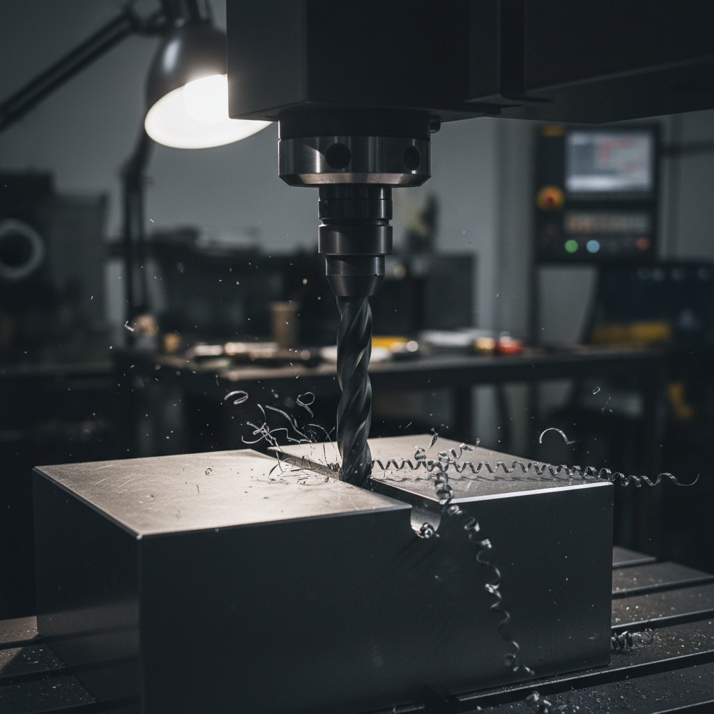
While sheet metal relies on bend geometry, CNC machining efficiency is largely dictated by how quickly a cutting tool can remove material while maintaining precision. Machine time is the primary cost driver here, and smart design choices directly influence how long a spindle stays in motion. To keep costs down, avoid designing deep, narrow pockets. A depth-to-width ratio greater than 4:1 typically requires specialized long-reach tools. These tools are prone to vibration and deflection, which forces the operator to use significantly slower feed rates to maintain accuracy. By keeping pockets shallow and wide, you allow for more aggressive cutting and better chip evacuation.
Internal corner radii also play a vital role in tool selection. Engineers should specify radii that are slightly larger than standard end mill sizes. For example, if a pocket is designed for a .250-inch tool, a corner radius of .130 inches allows the tool to navigate the turn without chattering or dwelling. This minor adjustment supports dependable manufacturing and production solutions by reducing machine wear and ensuring a smoother finish.
Every time a part must be flipped or rotated to access a new face, the setup cost increases. Designing parts that can be machined in one or two setups is far more economical than designs requiring 5-axis movement or multiple fixtures. According to industry data from Hubs, it is often more cost-effective to split a single complex component into multiple simpler parts. These individual components are easier to machine quickly and can be joined later through skilled fabrication and assembly, providing a high-performance result without the premium price tag of extreme geometric complexity.
How DFM Strategies Shrink Production Lead Times
Efficiency in production is measured by throughput, not just the cost of a single component. While cost savings are a natural byproduct of design for manufacturability, the primary advantage for many projects is the drastic reduction in lead times. When a design is optimized for fabrication, it bypasses the common rework loop. This loop occurs when a shop receives a file with unmanufacturable features, requiring technicians to halt work, notify the client, and wait for a redesign. A production-ready file moves directly to the floor, ensuring that dependable manufacturing and production solutions are executed without technical friction.
Material selection is another area where design choices impact the calendar. Lead times often stall due to raw material availability rather than machine capacity. By standardizing material choices, such as specifying common 6061 aluminum or 10-gauge mild steel, you ensure that the necessary stock is likely already on our shop floor or available through local suppliers for immediate delivery. Opting for specialty alloys or non-standard thicknesses can add weeks to a timeline while waiting for a custom mill run or a specialized shipment.
At Duchesne Manufacturing, we prioritize real-world performance, which requires moving parts through skilled fabrication and assembly as quickly as possible without sacrificing quality. A streamlined design eliminates the guesswork and technical bottlenecks that slow down production. If you are aiming for a tight launch window, you can contact Duchesne Manufacturing to review your design and identify opportunities to maximize throughput.
The Local Advantage: Why Collaborative Design Review Wins

At Duchesne Manufacturing, we bridge the gap between digital design and physical reality through a hands-on pre-production review. Our team in Duchesne, Utah, works closely with regional partners to examine CAD files before the first cut is made. This collaborative approach identifies potential failure points that a standard software check might miss, saving both time and material.
In the Intermountain West, components face unique environmental challenges. Parts used in regional agriculture, energy production, or heavy construction must endure extreme temperature swings, high UV exposure, and abrasive soil conditions. Integrating design for manufacturability at this stage ensures that your dependable manufacturing and production solutions account for real-world stress rather than just theoretical loads.
Proximity provides a level of accountability that offshore or distant suppliers cannot match. You have the ability to walk onto our shop floor and see the design-to-production transition in person, ensuring that skilled fabrication and assembly align exactly with your specifications. When you contact Duchesne Manufacturing, you gain a local partner who understands the rugged Utah landscape and is committed to delivering consistent, high-performance results.
Optimizing your part design is the most effective way to lower production costs and shorten lead times. By focusing on manufacturability early in the process, you ensure that every stage of production runs smoothly. If you would like expert assistance in refining your designs for better efficiency, our team is ready to support your goals. You can learn more about us and our commitment to quality manufacturing. We help you turn complex concepts into streamlined, cost effective realities.